Chapter 4 - Laboratory
Chapter 5 - Liquefier Acquisition and Control Computer
Peripheral files
View website PDF document
Hi-res video: Building a helium recovery system (5 minutes long)
YouTube video: Building a helium recovery system (5 minutes long)
List of many parts with prices and links [xls]
The Laboratory Manifold provides and easy way to pump and
purge back and fore lines, measure transfer exhaust flow, and route gasses from
various experiments to the Bladder Room Manifold. 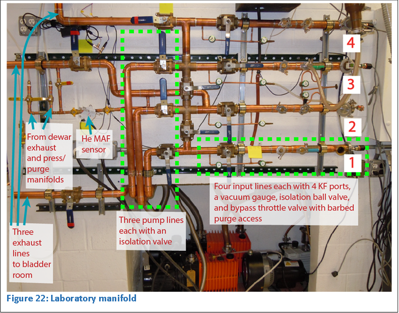 As
shown in Figure 22, the main laboratory manifold has four main input lines that
collect helium from experiments. Each input line has four KF ports for
connecting helium exhaust lines, relief valves, pressure gauges, or vacuum systems,
for example. Each input has a large isolating ball valve and a bypass line with
throttle valve. This small bypass line also provides an access with a barb and
shut-off valve, usually used for connecting purge gasses.
As
shown in Figure 22, the main laboratory manifold has four main input lines that
collect helium from experiments. Each input line has four KF ports for
connecting helium exhaust lines, relief valves, pressure gauges, or vacuum systems,
for example. Each input has a large isolating ball valve and a bypass line with
throttle valve. This small bypass line also provides an access with a barb and
shut-off valve, usually used for connecting purge gasses.
There are three pumping lines. Two lines are connected to a 2063 and 2033 Alcatel rotary vane pumps. One line is connected to a scroll pump.
Three helium exhaust lines run to the bladder room and interface with the Bladder Room Manifold. Each exhaust line has a large isolation valve. The middle helium exhaust line has a bypass line with an inline helium flow meter. The meter is used to monitor dewar-to-dewar transfer exhaust flow rate in the laboratory. The middle exhaust line is also to exhaust line two other laboratory manifolds, the Dewar Blow-off Manifold and the Pressurization/Vent Manifold as shown in Figure 22.
Any of the four input lines can be pumped with any of the three pumps or routed to any exhaust port. All fore- and back- lines can be evacuated and purged from the Laboratory Manifold.
Furthermore, the temperature of helium reservoirs can be lowered to below 2K by pumping with the scroll pump and recapturing the backline helium gas exhaust.
 The
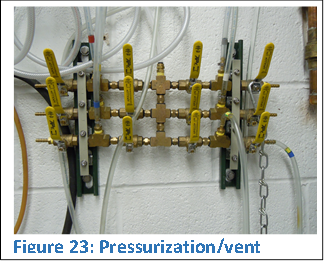
Pressurization/Vent manifold is a set of 6 lines each with two ball valves that
straddle a tee. Each of these tees has a tube that runs to various experimental
stations around the laboratory. The six manifold lines attach to one another
along the central “spine” as shown in Figure 23. The top of this spine has a
plastic exhaust tube that attaches to the main Laboratory Manifold. The ends of
each manifold line are barbed allowing users to attach compressed gasses from a
cylinder, usually helium or nitrogen.
The
Pressurization/Vent manifold is a set of 6 lines each with two ball valves that
straddle a tee. Each of these tees has a tube that runs to various experimental
stations around the laboratory. The six manifold lines attach to one another
along the central “spine” as shown in Figure 23. The top of this spine has a
plastic exhaust tube that attaches to the main Laboratory Manifold. The ends of
each manifold line are barbed allowing users to attach compressed gasses from a
cylinder, usually helium or nitrogen.
Therefore, either nitrogen or helium can be directed to any of the six stations. Any dewar or experimental vessels can be pressurized or purged. Pressurized helium vessels or dewars are vented and the exhaust routed to the middle helium exhaust line of the main Laboratory Manifold recovery line.
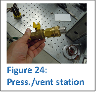 Each
station is equipped with a B-QF8 swagelok quick connect and shut-off ball valve,
like the one shown in Figure 24. Connection to the mobile helium dewars for
pressurizing and venting during transfers are foolproof. Converters to other
connectors have been made for other specialized purposes.
Each
station is equipped with a B-QF8 swagelok quick connect and shut-off ball valve,
like the one shown in Figure 24. Connection to the mobile helium dewars for
pressurizing and venting during transfers are foolproof. Converters to other
connectors have been made for other specialized purposes.
The manifold was assembled with XPando. It is not possible to modify it, but it will never leak!
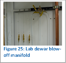 The
Laboratory Dewar Blow-off Manifold has three swagelock B-QC4 quick connects,
each attaching to a mobile dewar 0.5 PSI vent port. Each line has an isolation
valve. The combined dewar exhaust is directed through a plastic tube at the top
of the manifold, which connects to the middle exhaust line on the main
Laboratory Manifold.
The
Laboratory Dewar Blow-off Manifold has three swagelock B-QC4 quick connects,
each attaching to a mobile dewar 0.5 PSI vent port. Each line has an isolation
valve. The combined dewar exhaust is directed through a plastic tube at the top
of the manifold, which connects to the middle exhaust line on the main
Laboratory Manifold.
Therefore, mobile dewars exhaust directly into the bladder from the laboratory. This is different than the Liquefier Room where dewars exhaust directly into the liquefier.
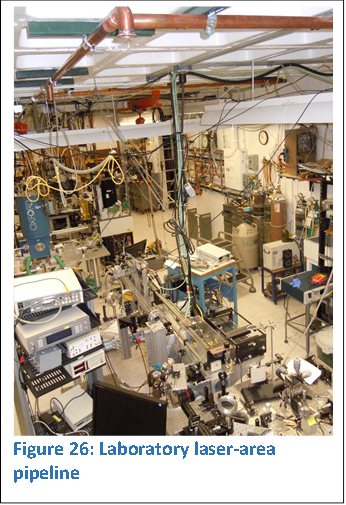 A
number of connections to the recovery system are possible around the
laboratory. A pipe is run on the ceiling above our laser area to various
experimental locations. Six KF ports allow connection to cryostats and
detectors for helium recapture. The exhaust from the pipeline feeds into input
line #2 of the main Laboratory Manifold.
A
number of connections to the recovery system are possible around the
laboratory. A pipe is run on the ceiling above our laser area to various
experimental locations. Six KF ports allow connection to cryostats and
detectors for helium recapture. The exhaust from the pipeline feeds into input
line #2 of the main Laboratory Manifold.
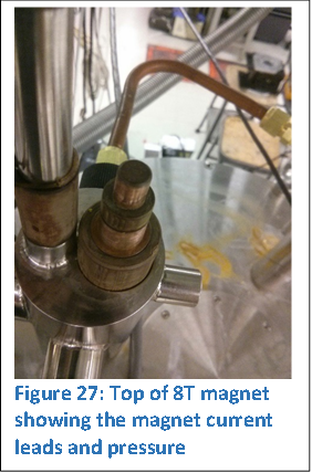 The
large amount of helium boil-off from our 8T split-coil magnet with optical
access was one of the motivating factors to install a laboratory helium
recovery system. While installing the recovery system, I designed and implemented
a new cold shield and sample actuator design that dramatically lowered helium
blow-off.
The
large amount of helium boil-off from our 8T split-coil magnet with optical
access was one of the motivating factors to install a laboratory helium
recovery system. While installing the recovery system, I designed and implemented
a new cold shield and sample actuator design that dramatically lowered helium
blow-off.
The helium reservoir leaked to atmosphere precluding the possibility of recovering the helium. The many leaks were repaired. Brass NPT fittings and compression fittings with copper tubing replaced several plastic hoses. The magnet leads leaked at every interface (4 of them) and were repaired: a dremel tool was used to cut a groove at the joint, an epoxy was applied, and a vacuum pulled on the helium reservoir which pulled the epoxy into the joints. The seals remain helium tight after thermally cycling the cryostat.
The magnet is operated with the exhaust fully open to the recovery system. When the magnet is not scanning, a low-pressure inline check valve is placed between the helium reservoir and the recovery system. This is accomplished with check valve connected between two of the main input lines of the main Laboratory Manifold.
Next: Chapter 5 - Liquefier Acquisition and Control Computer